Image Format Control
Region Of Interest
An image region of interest (ROI) lets you specify a portion of the image so that after each image is acquired only the pixel information from the specified portion is processed.
Use the following features to specify the location and size of the ROI. All values are in pixels.
OffsetX - Horizontal offset from the origin to the ROI.
Width - Width of the image provided by the device. This reflects the current ROI. The maximum value of this feature takes into account horizontal binning, decimation, or any other function changing the maximum horizontal dimensions of the image and is typically equal to WidthMax minus OffsetX.
OffsetY - Vertical offset from the origin to the ROI.
Height - Height of the image provided by the device. This reflects the current ROI. The maximum value of this feature takes into account vertical binning, decimation, or any other function changing the maximum vertical dimensions of the image and is typically equal to HeightMax minus OffsetY.
Binning/Decimation
Binning refers to the act of combining the signal from groups of photo-sensitive cells into a larger logical pixel. This is achieved by either adding (additive), averaging (average), or discarding (discard). Binning may be implemented in analog by the sensor or digitally by the Image Signal Processing engine (ISP).
Note: Binning and Decimation cannot operate simultaneously. For one to be active, the other must be inactive. Changes to binning features can only be made while the camera is not streaming.
Use the BinningSelector to choose the binning engine. This affects both horizontal and vertical binning. The choices are:
All - the total amount of binning. In this mode, the camera adjusts the sensor/ISP binning to achieve the best image quality with the fastest frame rate.
Sensor - the portion of binning implemented in analog by the sensor. Binning done by the sensor usually results in a higher frame rate. Unless otherwise specified, or unsupported, binning is done by the sensor by default.
ISP - the portion of binning implemented digitally by the ISP. Unless otherwise specified, binning is done by the ISP if sensor binning is is unsupported or compromises image quality.
Use BinningHorizontalMode and BinningVerticalMode to choose the algorithm to perform the combination. The choices are:
Additive - The response from the combined cells are added, resulting in increased sensitivity (a brighter image).
Average - The response from the combined cells are averaged, resulting in increased signal to noise ratio. Some sensors do not support average binning.
Use BinningHorizontal and BinningVertical to set the number of cells to combine. Binning values reduce the resolution of the image by a corresponding factor. A value of 1 indicates no binning. This must be set to 1 for decimation to be active.
Use DecimationSelector to choose the decimation engine. The choices are All or Sensor. Decimation cannot be done by the ISP.
DecimationHorizontalMode and DecimationVerticalMode indicate the algorithm to perform the reduction. There is only one decimation mode supported: Discard.
Use DecimationHorizontal and DecimationVertical to set the number of cells to discard. This value reduces the resolution of the image by only retaining a single pixel within a window whose size is the specified decimation factor. A value of 1 indicates no decimation. This must be set to 1 for binning to be active.
Binning/Decimation Feature Dependency
There are many feature dependencies which can affect binning. You can disable the ISP engine which would force all binning to be sensor controlled. However, some pixel formats (such as YUV and RGB) do not allow the ISP to be disabled, as it is required for color interpolation. In addition, not all sensors support average binning.
A simple hierarchical organization of the features means that features higher up have the greatest flexibility. Choices made at the top of the hierarchy adjust features downstream. The camera always attempts to achieve the best possible image quality.
Pixel Format
Format of the pixel provided by the camera. Use PixelFormat feature to select from a list of supported formats. (Not all formats are supported on all cameras.) Once a format is selected, the following values are derived:
PixelSize provides the total size in bits of the image's pixel.
PixelColorFilter is the type of color filter that is applied to the image. This only applies to bayer formats. The value is None for other formats.
PixelDynamicRangeMin is the minimum value that can be returned during the digitization process. This corresponds to the darkest value of the camera. For color cameras, this returns the smallest value that each color component can take.
PixelDynamicRangeMax is the maximum value that can be returned during the digitization process. This corresponds to the brightest value of the camera. For color cameras, this returns the largest value that each color component can take.
Note: For color cameras, the bayer pixel format is updated if Reverse X and Reverse Y are changed. For example, if the original pixel format is BayerRG8 and Reverse X is switched from Disabled to Enabled, then the pixel format is updated to BayerGR8.
Single Channel 8-bit and 16-bit Formats
| 8-bit Formats | Mono8 | 8-bit monochrome packed format |
| BayerGR8 | 8-bit bayer green red packed format | |
| BayerRG8 | 8-bit bayer red green packed format | |
| BayerGB8 | 8-bit bayer green blue packed format | |
| BayerBG8 | 8-bit bayer blue green packed format | |
| 16-bit Formats | Mono16 | 16-bit monochrome packed format |
| BayerGR16 | 16-bit bayer green red packed format | |
| BayerRG16 | 16-bit bayer red green packed format | |
| BayerGB16 | 16-bit bayer green blue packed format | |
| BayerBG16 | 16-bit bayer blue green packed format |
Single Channel 10-bit Formats
10-bit pixel formats have two different packing formats as defined by USB3 Vision and GigE Vision. Note: the packing format is not related to the interface of the camera. Both may be available on USB3 or GigE devices.
The USB3 Vision method is designated with a p. It is a 10-bit format with its bit-stream following the bit packing method illustrated in Figure 1. The first byte of the packed stream contains the eight least significant bits (lsb) of the first pixel. The two lsb of the second byte contain two msb of the first pixel, and the rest of the second byte is packed with the six lsb of the second pixel. The four msb of the second pixels fill into the four lsb of the third byte. The lsb of the third pixel fill in the rest of the third byte, and the remaining bits of the third pixel fill in the lsb of the fourth byte. The bytes are packed following this pattern. In general, pixels are packed into bytes in sequence from lsb, and four pixels pack into five bytes.
This packing format is applied to: Mono10p, BayerGR10p, BayerRG10p, BayerGB10p and BayerBG10p.

Figure 1. Packing two 10-bit pixels into three bytes.
The GigE Vision method is designated with Packed. It is a 10-bit format with its bit-stream following the bit packing method illustrated in Figure 2. The first byte of the packed stream contains the eight msb of the first pixel. The third byte contains the eight msb of the second pixel. The two lsb of the second byte contains two lsb of the first pixel, and the fifth and the sixth bits of the second byte are packed with the two lsb of the second pixel. The remaining bits in the second bytes are set to null.
This packing format is applied to: Mono10Packed, BayerGR10Packed, BayerRG10Packed, BayerGB10Packed and BayerBG10Packed.
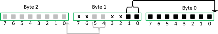
Figure 2. Packing two 10-bit pixels into three bytes.
Single Channel 12-bit Formats
12-bit pixel formats have two different packing formats as defined by USB3 Vision and GigE Vision. Note: the packing format is not related to the interface of the camera. Both may be available on USB3 or GigE devices.
The USB3 Vision method is designated with a p. It is a 12-bit format with its bit-stream following the bit packing method illustrated in Figure 3. The first byte of the packed stream contains the eight least significant bits (lsb) of the first pixel. The third byte contains the eight most significant bits (msb) of the second pixel. The four lsb of the second byte contains four msb of the first pixel, and the rest of the second byte is packed with the four lsb of the second pixel.
This packing format is applied to: Mono12p, BayerGR12p, BayerRG12p, BayerGB12p and BayerBG12p.
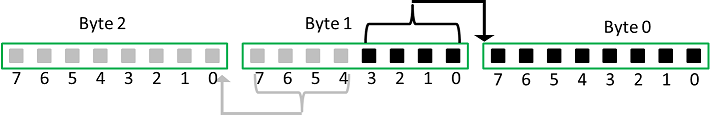
Figure 3. Packing two 12-bit pixels into three bytes.
The GigE Vision method is designated with Packed. It is a 12-bit format with its bit-stream following the bit packing method illustrated in Figure 4. The first byte of the packed stream contains the eight msb of the first pixel. The third byte contains the eight msb of the second pixel. The four lsb of the second byte contains four lsb of the first pixel, and the rest of the second byte is packed with the four lsb of the second pixel.
This packing format is applied to: Mono12Packed, BayerGR12Packed, BayerRG12Packed, BayerGB12Packed and BayerBG12Packed.
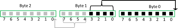
Figure 4. Packing two 12-bit pixels into three bytes.
Multi-Channel Formats - Color Models
For the following pixel formats, the color channels are packed in the order indicated:
| RGB8Packed | 8-bit red-green-blue packed format |
| BGR8 | 8-bit blue-green-red packed format |
| BGRa8 | 8-bit blue-green-red-alpha packed format |
For YCbCr and YUV pixel formats, the RGB to YCbCr transformation follows Equation 1 below:
| Y' | = | 0.299 R' | + | 0.587 G' | + | 0.114 B' | ||
| Cb | = | -0.16874 R' | – | 0.33126 G' | + | 0.5000 B' | + | 128 |
| Cr | = | 0.5000 R' | – | 0.41869 G' | – | 0.08131 B' | + | 128 |
YCbCr8 / YUV444Packed
8-bit Y-Cb-Cr 4:4:4 format (Figure 5). No sub-sampling on Y, Cb or Cr. The values of Y, Cb and Cr cover the full range from 0 to 255 if the input R, G and B values are in the range of [0, 255].
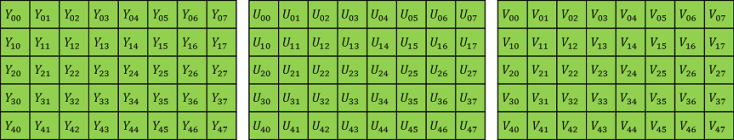
Figure 5. Y-Cb-Cr 4:4:4 format.
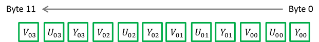
Figure 6. Packing format for YCbCr8.
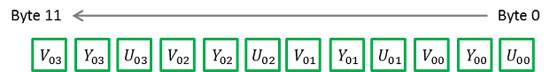
Figure 7. Packing format for YUV444Packed.
YCbCr422_8 / YUV422Packed
8-bit Y-Cb-Cr 4:2:2 format (Figure 8). No sub-sampling on Y. Cb and Cr are sub-sampled by a factor of 2 in the horizontal direction, but no sub-sampling in the vertical direction. The values of Y, Cb and Cr cover the full range from 0 to 255 if the input R, G and B values are in the range of [0, 255].
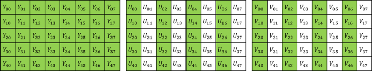
Figure 8. Y-Cb-Cr 4:2:2 format.
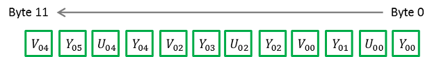
Figure 9. Packing format for YCbCr422_8.
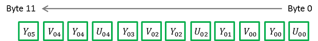
Figure 10. Packing format for YUV422Packed.
YCbCr411_8 / YUV411Packed
8-bit Y-Cb-Cr 4:1:1 format (Figure 11). No sub-sampling on Y. Cb and Cr are sub-sampled by a factor of 4 in the horizontal direction, but no sub-sampling in the vertical direction. The values of Y, Cb and Cr cover the full range from 0 to 255 if the input R, G and B values are in the range of [0, 255].
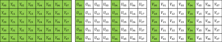
Figure 11. Y-Cb-Cr 4:1:1 format.
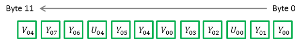
Figure 12. Packing format for YCbCr411_8.
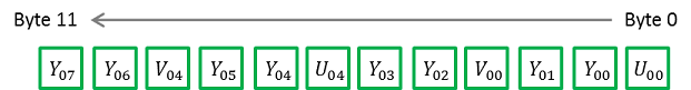
Figure 13. Packing format for YUV411Packed.
ADC Bit Depth
All camera sensors incorporate an analog to digital converter (ADC) to digitize the images.
The camera's ADC is configured to a fixed bit output. This is not the same as pixel size. If the pixel format selected has fewer bits per pixel than the ADC output, the least significant bits are dropped. If the pixel format selected has greater bits per pixel than the ADC output, the least significant bits are padded and can be discarded by the user. Image data is left-aligned across a 2-byte format.
For example, for a 12-bit output, the least significant 4 bits are padded in order to fill 2 bytes (0xFFF0).
A 10-bit conversion produces 1,024 possible values between 0 and 65,472.
A 12-bit conversion produces 4,096 possible values between 0 and 65,520.
A 14-bit conversion produces 16,384 possible values between 0 and 65,532.
Some image sensors support multiple ADC bit depths. A higher ADC bit depth results in better image quality but slower maximum frame rate. Stop acquisition then use the ADC Bit Depth control to make a selection.
Test Pattern
The camera is capable of outputting continuous static images for testing and development purposes.
Use the TestPatternGeneratorSelector feature to choose which test pattern to control.
Sensor produces a test pattern that varies based on the image sensor.
Pipeline Start inserts a test pattern at the start of the camera's image processing pipeline.
Set the TestPattern feature to Off to disable the selected test pattern generator.
When Sensor is selected, create a test pattern by setting the TestPattern feature to Sensor Test Pattern.
When Pipeline Start is selected, create a test pattern by setting the TestPattern feature to Increment or Variable Frame Sequence. The Increment test pattern increases the pixel value by one 8-bit greyscale value at each pixel location, wrapping around to zero after it reaches 255.
The Variable Frame Sequence option generates a sequence of frames containing varying test pattern. The sequence resets at the start of acquisition.
Both test pattern generators can be enabled at the same time, however, the Pipeline Start test pattern overwrites the Sensor test pattern.
Most image processing features (such as Gamma, Balance Ratio, and others) are still available when the test pattern is on and can alter the test pattern image. Some features for controlling the sensor do not affect the test pattern image, such as Exposure Time, Gain, and analog Black Level. It is recommended to turn Exposure Auto and Gain Auto Off when using a test pattern, as those features do not function properly when the test pattern is on.
Note that the test pattern generators must be set to Off to get the actual image data from the sensor.
Reverse X
When Reverse X is enabled, it horizontally flips the image sent by the camera. The region of interest is applied after flipping.
For color cameras, the bayer pixel format may be changed after flipping. For example, BayerRG16 is changed to BayerGR16.
Reverse Y
When Reverse Y is enabled, it vertically flips the image sent by the camera. The region of interest is applied after flipping.
For color cameras, the bayer pixel format may be changed after flipping. For example, BayerRG16 is changed to BayerGB16.
Summary Table
| Name | Interface | Access | Visibility | Description |
|---|---|---|---|---|
| Sensor Width | IInteger | RO | Expert | Effective width of the sensor in pixels. |
| Sensor Height | IInteger | RO | Expert | Effective height of the sensor in pixels. |
| Width Max | IInteger | Expert | Maximum width of the image (in pixels). The dimension is calculated after horizontal binning. WidthMax does not take into account the current Region of interest (Width or OffsetX). | |
| Height Max | IInteger | Expert | Maximum height of the image (in pixels). This dimension is calculated after vertical binning. HeightMax does not take into account the current Region of interest (Height or OffsetY). | |
| Width | IInteger | Beginner | Width of the image provided by the device (in pixels). | |
| Height | IInteger | Beginner | Height of the image provided by the device (in pixels). | |
| Offset X | IInteger | Beginner | Horizontal offset from the origin to the ROI (in pixels). | |
| Offset Y | IInteger | Beginner | Vertical offset from the origin to the ROI (in pixels). | |
| Pixel Format | IEnumeration | Beginner | Format of the pixel provided by the camera. | |
| Pixel Size | IEnumeration | RO | Expert | Total size in bits of a pixel of the image. |
| Pixel Color Filter | IEnumeration | RO | Expert | Type of color filter that is applied to the image. Only applies to Bayer pixel formats. All others have no color filter. |
| Pixel Dynamic Range Min | IInteger | RO | Expert | Minimum value that can be returned during the digitization process. This corresponds to the darkest value of the camera. For color cameras, this returns the smallest value that each color component can take. |
| Pixel Dynamic Range Max | IInteger | RO | Expert | Maximum value that can be returned during the digitization process. This corresponds to the brightest value of the camera. For color cameras, this returns the biggest value that each color component can take. |
| ISP Enable | IBoolean | RW | Expert | Controls whether the image processing core is used for optional pixel format mode (i.e. mono). |
| Binning Selector | IEnumeration | Beginner | Selects which binning engine is controlled by the BinningHorizontal and BinningVertical features. | |
| Binning Horizontal Mode [Binning Selector] | IEnumeration | Expert | ||
| Binning Vertical Mode [Binning Selector] | IEnumeration | Expert | ||
| Binning Horizontal [Binning Selector] | IInteger | Beginner | Number of horizontal photo-sensitive cells to combine together. This reduces the horizontal resolution (width) of the image. A value of 1 indicates that no horizontal binning is performed by the camera. This value must be 1 for decimation to be active. | |
| Binning Vertical [Binning Selector] | IInteger | Beginner | Number of vertical photo-sensitive cells to combine together. This reduces the vertical resolution (height) of the image. A value of 1 indicates that no vertical binning is performed by the camera. This value must be 1 for decimation to be active. | |
| Decimation Selector | IEnumeration | Beginner | Selects which decimation layer is controlled by the DecimationHorizontal and DecimationVertical features. | |
| Decimation Horizontal Mode [Decimation Selector] | IEnumeration | Expert | The mode used to reduce the horizontal resolution when DecimationHorizontal is used. The current implementation only supports a single decimation mode: Discard. Average should be achieved via Binning. | |
| Decimation Vertical Mode [Decimation Selector] | IEnumeration | Expert | The mode used to reduce the vertical resolution when DecimationVertical is used. The current implementation only supports a single decimation mode: Discard. Average should be achieved via Binning. | |
| Decimation Horizontal [Decimation Selector] | IInteger | Beginner | Horizontal decimation of the image. This reduces the horizontal resolution (width) of the image by only retaining a single pixel within a window whose size is the decimation factor specified here. A value of 1 indicates that no horizontal decimation is performed by the camera. This value must be 1 for binning to be active. | |
| Decimation Vertical [Decimation Selector] | IInteger | Beginner | Vertical decimation of the image. This reduces the vertical resolution (height) of the image by only retaining a single pixel within a window whose size is the decimation factor specified here. A value of 1 indicates that no vertical decimation is performed by the camera. This value must be 1 for binning to be active. | |
| Reverse X | IBoolean | RW | Expert | Horizontally flips the image sent by the device. The region of interest is applied after flipping. For color cameras the bayer pixel format is affected. For example, BayerRG16 changes to BayerGR16. |
| Reverse Y | IBoolean | RW | Expert | Vertically flips the image sent by the device. The region of interest is applied after flipping. For color cameras the bayer pixel format is affected. For example, BayerRG16 changes to BayerGB16. |
| Test Pattern Generator Selector | IEnumeration | Selects which test pattern generator is controlled by the TestPattern feature. | ||
| Test Pattern [Test Pattern Generator Selector] | IEnumeration | Selects the type of test pattern that is generated by the device as image source. | ||
| ADC Bit Depth | IEnumeration | Beginner | Selects which ADC bit depth to use. A higher ADC bit depth results in better image quality but slower maximum frame rate. |
Image Format Control Features
Sensor Width
Effective width of the sensor in pixels.
| Property | Value |
|---|---|
| Name | SensorWidth |
| Interface | IInteger |
| Access | RO |
| Unit | |
| Visibility | Expert |
| Value | 4072 |
Sensor Height
Effective height of the sensor in pixels.
| Property | Value |
|---|---|
| Name | SensorHeight |
| Interface | IInteger |
| Access | RO |
| Unit | |
| Visibility | Expert |
| Value | 3046 |
Width Max
Maximum width of the image (in pixels). The dimension is calculated after horizontal binning. WidthMax does not take into account the current Region of interest (Width or OffsetX).
| Property | Value |
|---|---|
| Name | WidthMax |
| Interface | IInteger |
| Access | |
| Unit | |
| Visibility | Expert |
Height Max
Maximum height of the image (in pixels). This dimension is calculated after vertical binning. HeightMax does not take into account the current Region of interest (Height or OffsetY).
| Property | Value |
|---|---|
| Name | HeightMax |
| Interface | IInteger |
| Access | |
| Unit | |
| Visibility | Expert |
Width
Width of the image provided by the device (in pixels).
| Property | Value |
|---|---|
| Name | Width |
| Interface | IInteger |
| Access | |
| Unit | |
| Visibility | Beginner |
Height
Height of the image provided by the device (in pixels).
| Property | Value |
|---|---|
| Name | Height |
| Interface | IInteger |
| Access | |
| Unit | |
| Visibility | Beginner |
Offset X
Horizontal offset from the origin to the ROI (in pixels).
| Property | Value |
|---|---|
| Name | OffsetX |
| Interface | IInteger |
| Access | |
| Unit | |
| Visibility | Beginner |
Offset Y
Vertical offset from the origin to the ROI (in pixels).
| Property | Value |
|---|---|
| Name | OffsetY |
| Interface | IInteger |
| Access | |
| Unit | |
| Visibility | Beginner |
Pixel Format
Format of the pixel provided by the camera.
| Property | Value |
|---|---|
| Name | PixelFormat |
| Interface | IEnumeration |
| Access | |
| Visibility | Beginner |
| Enumeration Values |
|---|
| Mono8 |
| Mono16 |
| RGB8Packed |
| BayerGR8 |
| BayerRG8 |
| BayerGB8 |
| BayerBG8 |
| BayerGR16 |
| BayerRG16 |
| BayerGB16 |
| BayerBG16 |
| Mono10Packed |
| BayerGR10Packed |
| BayerRG10Packed |
| BayerGB10Packed |
| BayerBG10Packed |
| Mono12Packed |
| BayerGR12Packed |
| BayerRG12Packed |
| BayerGB12Packed |
| BayerBG12Packed |
| YUV411Packed |
| YUV422Packed |
| YUV444Packed |
| Mono10p |
| BayerGR10p |
| BayerRG10p |
| BayerGB10p |
| BayerBG10p |
| Mono12p |
| BayerGR12p |
| BayerRG12p |
| BayerGB12p |
| BayerBG12p |
| YCbCr8 |
| YCbCr422_8 |
| YCbCr411_8 |
| BGR8 |
| BGRa8 |
Pixel Size
Total size in bits of a pixel of the image.
| Property | Value |
|---|---|
| Name | PixelSize |
| Interface | IEnumeration |
| Access | RO |
| Visibility | Expert |
| Enumeration Values |
|---|
| Bpp1 |
| Bpp2 |
| Bpp4 |
| Bpp8 |
| Bpp10 |
| Bpp12 |
| Bpp14 |
| Bpp16 |
| Bpp20 |
| Bpp24 |
| Bpp30 |
| Bpp32 |
| Bpp36 |
| Bpp48 |
| Bpp64 |
| Bpp96 |
Pixel Color Filter
Type of color filter that is applied to the image. Only applies to Bayer pixel formats. All others have no color filter.
| Property | Value |
|---|---|
| Name | PixelColorFilter |
| Interface | IEnumeration |
| Access | RO |
| Visibility | Expert |
| Enumeration Values |
|---|
| None |
| BayerRG |
| BayerGB |
| BayerGR |
| BayerBG |
Pixel Dynamic Range Min
Minimum value that can be returned during the digitization process. This corresponds to the darkest value of the camera. For color cameras, this returns the smallest value that each color component can take.
| Property | Value |
|---|---|
| Name | PixelDynamicRangeMin |
| Interface | IInteger |
| Access | RO |
| Unit | |
| Visibility | Expert |
| Value | 0 |
Pixel Dynamic Range Max
Maximum value that can be returned during the digitization process. This corresponds to the brightest value of the camera. For color cameras, this returns the biggest value that each color component can take.
| Property | Value |
|---|---|
| Name | PixelDynamicRangeMax |
| Interface | IInteger |
| Access | RO |
| Unit | |
| Visibility | Expert |
ISP Enable
Controls whether the image processing core is used for optional pixel format mode (i.e. mono).
| Property | Value |
|---|---|
| Name | IspEnable |
| Interface | IBoolean |
| Access | RW |
| Visibility | Expert |
Binning Selector
Selects which binning engine is controlled by the BinningHorizontal and BinningVertical features.
| Property | Value |
|---|---|
| Name | BinningSelector |
| Interface | IEnumeration |
| Access | |
| Visibility | Beginner |
| Enumeration Values |
|---|
| All |
| Sensor |
| ISP |
Binning Horizontal Mode
| Property | Value |
|---|---|
| Name | BinningHorizontalMode [Binning Selector] |
| Interface | IEnumeration |
| Access | |
| Visibility | Expert |
| Enumeration Values |
|---|
| Sum |
| Average |
Binning Vertical Mode
| Property | Value |
|---|---|
| Name | BinningVerticalMode [Binning Selector] |
| Interface | IEnumeration |
| Access | |
| Visibility | Expert |
| Enumeration Values |
|---|
| Sum |
| Average |
Binning Horizontal
Number of horizontal photo-sensitive cells to combine together. This reduces the horizontal resolution (width) of the image. A value of 1 indicates that no horizontal binning is performed by the camera. This value must be 1 for decimation to be active.
| Property | Value |
|---|---|
| Name | BinningHorizontal [Binning Selector] |
| Interface | IInteger |
| Access | |
| Unit | |
| Visibility | Beginner |
Binning Vertical
Number of vertical photo-sensitive cells to combine together. This reduces the vertical resolution (height) of the image. A value of 1 indicates that no vertical binning is performed by the camera. This value must be 1 for decimation to be active.
| Property | Value |
|---|---|
| Name | BinningVertical [Binning Selector] |
| Interface | IInteger |
| Access | |
| Unit | |
| Visibility | Beginner |
Decimation Selector
Selects which decimation layer is controlled by the DecimationHorizontal and DecimationVertical features.
| Property | Value |
|---|---|
| Name | DecimationSelector |
| Interface | IEnumeration |
| Access | |
| Visibility | Beginner |
| Enumeration Values |
|---|
| All |
| Sensor |
Decimation Horizontal Mode
The mode used to reduce the horizontal resolution when DecimationHorizontal is used. The current implementation only supports a single decimation mode: Discard. Average should be achieved via Binning.
| Property | Value |
|---|---|
| Name | DecimationHorizontalMode [Decimation Selector] |
| Interface | IEnumeration |
| Access | |
| Visibility | Expert |
| Enumeration Values |
|---|
| Discard |
Decimation Vertical Mode
The mode used to reduce the vertical resolution when DecimationVertical is used. The current implementation only supports a single decimation mode: Discard. Average should be achieved via Binning.
| Property | Value |
|---|---|
| Name | DecimationVerticalMode [Decimation Selector] |
| Interface | IEnumeration |
| Access | |
| Visibility | Expert |
| Enumeration Values |
|---|
| Discard |
Decimation Horizontal
Horizontal decimation of the image. This reduces the horizontal resolution (width) of the image by only retaining a single pixel within a window whose size is the decimation factor specified here. A value of 1 indicates that no horizontal decimation is performed by the camera. This value must be 1 for binning to be active.
| Property | Value |
|---|---|
| Name | DecimationHorizontal [Decimation Selector] |
| Interface | IInteger |
| Access | |
| Unit | |
| Visibility | Beginner |
Decimation Vertical
Vertical decimation of the image. This reduces the vertical resolution (height) of the image by only retaining a single pixel within a window whose size is the decimation factor specified here. A value of 1 indicates that no vertical decimation is performed by the camera. This value must be 1 for binning to be active.
| Property | Value |
|---|---|
| Name | DecimationVertical [Decimation Selector] |
| Interface | IInteger |
| Access | |
| Unit | |
| Visibility | Beginner |
Reverse X
Horizontally flips the image sent by the device. The region of interest is applied after flipping. For color cameras the bayer pixel format is affected. For example, BayerRG16 changes to BayerGR16.
| Property | Value |
|---|---|
| Name | ReverseX |
| Interface | IBoolean |
| Access | RW |
| Visibility | Expert |
Reverse Y
Vertically flips the image sent by the device. The region of interest is applied after flipping. For color cameras the bayer pixel format is affected. For example, BayerRG16 changes to BayerGB16.
| Property | Value |
|---|---|
| Name | ReverseY |
| Interface | IBoolean |
| Access | RW |
| Visibility | Expert |
Test Pattern Generator Selector
Selects which test pattern generator is controlled by the TestPattern feature.
| Property | Value |
|---|---|
| Name | TestPatternGeneratorSelector |
| Interface | IEnumeration |
| Access | |
| Visibility |
| Enumeration Values |
|---|
| Sensor |
| PipelineStart |
Test Pattern
Selects the type of test pattern that is generated by the device as image source.
| Property | Value |
|---|---|
| Name | TestPattern [Test Pattern Generator Selector] |
| Interface | IEnumeration |
| Access | |
| Visibility |
| Enumeration Values |
|---|
| Off |
| Increment |
| SensorTestPattern |
ADC Bit Depth
Selects which ADC bit depth to use. A higher ADC bit depth results in better image quality but slower maximum frame rate.
| Property | Value |
|---|---|
| Name | AdcBitDepth |
| Interface | IEnumeration |
| Access | |
| Visibility | Beginner |
| Enumeration Values |
|---|
| Bit10 |
| Bit12 |
_242x41.jpg)