Digital IO Control
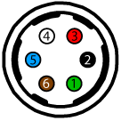
The camera is equipped with a 6-pin GPIO connector on the back of the case. The connector is a Hirose HR10A-7R-6PB, the mating connector is a Hirose HR10A-7P-6S(73).
| Diagram | Color | Pin | Line | Function | Description |
|---|---|---|---|---|---|
|
Green | 1 | 3 | Power / Input | +12 V DC Camera Power / Non-isolated input |
| Black | 2 | 0 | Opto Input 1 | Opto-isolated input | |
| Red | 3 | 2 | NC / +3.3 V / GPIO | +3.3 V output. Current 120 mA (nominal) Firmware enabled / Non-isolated I/O | |
| White | 4 | 1 | Opto Output 1 | Opto-isolated output | |
| Blue | 5 | N/A | Opto GND | Ground for opto-isolated I/O, not connected to camera ground | |
| Brown | 6 | N/A | GND | DC camera power ground |
This section describes how to configure the camera's general purpose digital input and outputs (sometimes referred to as GPIO).
Use LineSelector to choose which of the 4 lines to configure. All the features listed beneath it are controllable on a per line basis.
Use Line Mode to control the direction - either Input or Output - of the selected I/O line.
Use 3.3V Enable to supply external circuits with power. This is different than standard logic outputs in that it is comparatively slow to switch but can supply a more significant amount of power. This is only available on some pins.
Use LineInverter to control a logic inverter on the selected line.
LineStatus indicates the current status of the selected line. A checked status (enabled) indicates logic high. An unchecked status (disabled) indicates logic low. Since this node must be polled to get its status it should not be used as a real time control for reading internal signals.
LineStatusAll is a hexadecimal representation of all the line status bits (Line 0 status corresponds to bit 0, Line 1 status with bit 1, etc). This allows simultaneous reading of all line statuses at once.
Use the LineInputFilterSelector to choose a filter. Filters are unique per line. Use LineFilterWidth to set the width of the filter in microseconds. There are two choices of filter:
Deglitch - designed to filter out any noise or other spurious signals on the line, it does not consider the state to have transitioned until after the Filter Width time has expired. This means that Deglitch introduces a delay in the signal.
Debounce - designed to filter out rapid connecting and disconnecting common in mechanical switches. This means that Debounce considers the first edge as valid and won't allow a subsequent change of state until after the debounce time has elapsed.
Note: The Deglitch filter is applied before Debounce filter.
Use LineSource to control what signal is output on the line when the Line Mode is set to output. The choices are:
Other Lines - creates a loop back
User Outputs - outputs user controllable internal signals
Counter Active - shows when a counter is in use
Logic Blocks - drives the lines
Exposure Active - indicates when the image sensor is exposing
Frame Trigger Wait - indicates when the camera is ready to accept a new Frame Start trigger
If a User Output is selected as a Line Source, use UserOutputSelector to select which bit to use as internal signals within the camera. Use UserOutputValue to set the selected user output to logic high (enabled) or logic low (disabled).
UserOutputValueAll is a hexadecimal representation of all the user output bits (User Output 0 corresponds to bit 0, User Output 1 with bit 1, etc). Reading or writing User Output Value All allows simultaneous setting or reading of all user outputs at once.
LineFormat is read only and indicates what type of circuit the selected line has. The options for Line Format are:
Tri State - indicates the line is not driven. This is typical for digital inputs.
Opto Coupled - indicates that an opto isolator is being used to isolated the external circuitry from the internal camera electronics.
Open Drain - indicates there is an internal MOSFET that will pull the pin low but requires an external pull up resistor to produce a logic level high signal. This is typical for digital outputs.
Summary Table
| Name | Interface | Access | Visibility | Description |
|---|---|---|---|---|
| Line Selector | IEnumeration | Expert | Selects the physical line (or pin) of the external device connector to configure | |
| Line Mode [Line Selector] | IEnumeration | Expert | Controls if the physical Line is used to Input or Output a signal. | |
| 3.3V Enable [Line Selector] | IBoolean | RW | Guru | Internally generated 3.3V rail. Enable to supply external circuits with power. This is different than standard logic outputs in that it is comparatively slow to switch but can supply a more significant amount of power. This is only available on some pins. |
| Line Inverter [Line Selector] | IBoolean | RW | Expert | Controls the inversion of the signal of the selected input or output line. |
| Line Status [Line Selector] | IBoolean | RO | Expert | Returns the current status of the selected input or output Line |
| Line Status All | IInteger | RO | Expert | Returns the current status of all the line status bits in a hexadecimal representation (Line 0 status corresponds to bit 0, Line 1 status with bit 1, etc). This allows simultaneous reading of all line statuses at once. |
| Input filter Selector [Line Selector] | IEnumeration | Expert | Selects the kind of input filter to configure: Deglitch or Debounce. | |
| Line Filter Width [Input filter Selector] | IFloat | Expert | Filter width in microseconds for the selected line and filter combination | |
| Line Source [Line Selector] | IEnumeration | Expert | Selects which internal acquisition or I/O source signal to output on the selected line. LineMode must be Output. | |
| Line Format [Line Selector] | IEnumeration | RO | Expert | Displays the current electrical format of the selected physical input or output Line. |
| Exposure Active Mode | IEnumeration | RW | Expert | Control sensor active exposure mode. |
| User Output Selector | IEnumeration | Expert | Selects which bit of the User Output register is set by UserOutputValue. | |
| User Output Value [User Output Selector] | IBoolean | RW | Expert | Value of the selected user output, either logic high (enabled) or logic low (disabled). |
| User Output Value All | IInteger | Expert | Returns the current status of all the user output status bits in a hexadecimal representation (UserOutput 0 status corresponds to bit 0, UserOutput 1 status with bit 1, etc). This allows simultaneous reading of all user output statuses at once. |
Digital IO Control Features
Line Selector
Selects the physical line (or pin) of the external device connector to configure
| Property | Value |
|---|---|
| Name | LineSelector |
| Interface | IEnumeration |
| Access | |
| Visibility | Expert |
| Enumeration Values |
|---|
| Line0 |
| Line1 |
| Line2 |
| Line3 |
Line Mode
Controls if the physical Line is used to Input or Output a signal.
| Property | Value |
|---|---|
| Name | LineMode [Line Selector] |
| Interface | IEnumeration |
| Access | |
| Visibility | Expert |
| Enumeration Values |
|---|
| Input |
| Output |
3.3V Enable
Internally generated 3.3V rail. Enable to supply external circuits with power. This is different than standard logic outputs in that it is comparatively slow to switch but can supply a more significant amount of power. This is only available on some pins.
| Property | Value |
|---|---|
| Name | V3_3Enable [Line Selector] |
| Interface | IBoolean |
| Access | RW |
| Visibility | Guru |
Line Inverter
Controls the inversion of the signal of the selected input or output line.
| Property | Value |
|---|---|
| Name | LineInverter [Line Selector] |
| Interface | IBoolean |
| Access | RW |
| Visibility | Expert |
Line Status
Returns the current status of the selected input or output Line
| Property | Value |
|---|---|
| Name | LineStatus [Line Selector] |
| Interface | IBoolean |
| Access | RO |
| Visibility | Expert |
Line Status All
Returns the current status of all the line status bits in a hexadecimal representation (Line 0 status corresponds to bit 0, Line 1 status with bit 1, etc). This allows simultaneous reading of all line statuses at once.
| Property | Value |
|---|---|
| Name | LineStatusAll |
| Interface | IInteger |
| Access | RO |
| Unit | |
| Visibility | Expert |
Input filter Selector
Selects the kind of input filter to configure: Deglitch or Debounce.
| Property | Value |
|---|---|
| Name | LineInputFilterSelector [Line Selector] |
| Interface | IEnumeration |
| Access | |
| Visibility | Expert |
| Enumeration Values |
|---|
| Deglitch |
| Debounce |
Line Filter Width
Filter width in microseconds for the selected line and filter combination
| Property | Value |
|---|---|
| Name | LineFilterWidth [Input filter Selector] |
| Interface | IFloat |
| Access | |
| Unit | us |
| Visibility | Expert |
Line Source
Selects which internal acquisition or I/O source signal to output on the selected line. LineMode must be Output.
| Property | Value |
|---|---|
| Name | LineSource [Line Selector] |
| Interface | IEnumeration |
| Access | |
| Visibility | Expert |
| Enumeration Values |
|---|
| Off |
| Line0 |
| Line1 |
| Line2 |
| Line3 |
| UserOutput0 |
| UserOutput1 |
| UserOutput2 |
| UserOutput3 |
| Counter0Active |
| Counter1Active |
| LogicBlock0 |
| LogicBlock1 |
| ExposureActive |
| FrameTriggerWait |
| PPSSignal |
| SerialPort0 |
Line Format
Displays the current electrical format of the selected physical input or output Line.
| Property | Value |
|---|---|
| Name | LineFormat [Line Selector] |
| Interface | IEnumeration |
| Access | RO |
| Visibility | Expert |
| Enumeration Values |
|---|
| TriState |
| OptoCoupled |
| OpenDrain |
Exposure Active Mode
Control sensor active exposure mode.
| Property | Value |
|---|---|
| Name | ExposureActiveMode |
| Interface | IEnumeration |
| Access | RW |
| Visibility | Expert |
| Enumeration Values |
|---|
| Line1 |
| AnyPixels |
| AllPixels |
User Output Selector
Selects which bit of the User Output register is set by UserOutputValue.
| Property | Value |
|---|---|
| Name | UserOutputSelector |
| Interface | IEnumeration |
| Access | |
| Visibility | Expert |
| Enumeration Values |
|---|
| UserOutput0 |
| UserOutput1 |
| UserOutput2 |
| UserOutput3 |
User Output Value
Value of the selected user output, either logic high (enabled) or logic low (disabled).
| Property | Value |
|---|---|
| Name | UserOutputValue [User Output Selector] |
| Interface | IBoolean |
| Access | RW |
| Visibility | Expert |
User Output Value All
Returns the current status of all the user output status bits in a hexadecimal representation (UserOutput 0 status corresponds to bit 0, UserOutput 1 status with bit 1, etc). This allows simultaneous reading of all user output statuses at once.
| Property | Value |
|---|---|
| Name | UserOutputValueAll |
| Interface | IInteger |
| Access | |
| Unit | |
| Visibility | Expert |
_242x41.jpg)