Installing Your Board-level Dragonfly Camera
1. Prepare the Lens Mount

|
The board-level models can use CS-mounts or S-mounts. |
2. Remove sticker and install Lens Mount

|
The sensor is covered with a protective sticker. Remove the sticker. If any residue is present, clean the sensor surface with a non-abrasive cotton swab and isopropyl alcohol cleaning solution. Immediately install the image board over the prepared lens mount. |
3. Install the locking bracket (optional)

|
An optional bracket (ACC-01-0020) can be installed over the interface connector for locking the USB3 cable to the camera. |
4. Install a Heatsink

|
A heatsink is mandatory for board-level and partial cased models. |
5. Connect the interface Card and Cable to the camera
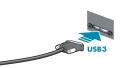
|
Plug the interface cable into the host controller card and the camera. If using a locking bracket, the cable jack screws can be used for a secure connection. |
6. Attach a Lens

|
Unscrew the dust cap from the lens holder to install a lens. |
7. Plug in the GPIO connector if required

|
GPIO can be used for trigger and strobe. |
8. Confirm Successful Installation
When the camera is first connected, the operating system automatically installs the camera driver. Camera drivers are available with the Spinnaker SDK installation.
Run the SpinView application: StartÒTeledyne Spinnaker SDKÒSpinView
The SpinView application can be used to test the camera's image acquisition capabilities.
Changes to your camera's installation configuration can be made using the SpinView application.
Installing Your Cased Dragonfly Camera
1. Install the Tripod Mounting Bracket (optional)

|
The ASA and ISO-compliant tripod mounting bracket attaches to the camera using the included screws. |
2. Attach a Lens

|
Unscrew the dust cap or remove the protective sticker from the lens holder to install a lens. If any residue is present, clean the surface with a non-abrasive cotton swab and isopropyl alcohol cleaning solution. Immediately attach the lens. |
3. Connect the interface Card and Cable to the Camera
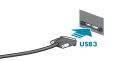
|
Plug the interface cable into the host controller card and the camera. The cable jack screws can be used for a secure connection. |
4. Plug in the GPIO connector if required

|
GPIO can be used for trigger and strobe. |
5. Confirm Successful Installation
When the camera is first connected, the operating system automatically installs the camera driver. Camera drivers are available with the Spinnaker SDK installation.
Run the SpinView application: StartÒTeledyne Spinnaker SDKÒSpinView
The SpinView application can be used to test the camera's image acquisition capabilities.
Changes to your camera's installation configuration can be made using the SpinView application.