Input/Output Control
General Purpose Input/Output (GPIO)
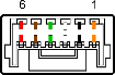
The camera is equipped with a 6-pin GPIO connector. The connector is a JST BM06B-NSHSS-TBT (LF)(SN), the mating connector is a JST NSHR-06V-S.
| Diagram | Color1 | Pin | Line | Function | Description | Parameters | Min | Max | Unit |
|---|---|---|---|---|---|---|---|---|---|
|
Orange | 12 | 0 | GPIO0 | Non-isolated Input/Output TXD (output) for 1.8 V UART |
Input Low Level | 0 | 1.4 | V |
| Input High Level | 2.6 | 24 | V | ||||||
| Propagation Delay | 1 | µs | |||||||
| Output Low Current | 25 | mA | |||||||
| Output High Level | 0 | 24 | V | ||||||
| Black | 22 | 1 | GPIO1 | Non-isolated Input/Output RXD (input) for 1.8 V UART |
Input Low Level | 0 | 1.4 | V | |
| Input High Level | 2.6 | 24 | V | ||||||
| Propagation Delay | 1 | µs | |||||||
| Output Low Current | 25 | mA | |||||||
| Output High Level | 0 | 24 | V | ||||||
| White | 3 | 2 | GPIO2 | Non-isolated Input/Output | Input Low Level | 0 | 1.4 | V | |
| Input High Level | 2.6 | 24 | V | ||||||
| Propagation Delay | 1 | µs | |||||||
| Output Low Current | 25 | mA | |||||||
| Output High Level | 0 | 24 | V | ||||||
| Green | 4 | 3 | GPIO3 | Non-isolated Input/Output | Input Low Level | 0 | 1.4 | V | |
| Input High Level | 2.6 | 24 | V | ||||||
| Propagation Delay | 1 | µs | |||||||
| Output Low Current | 25 | mA | |||||||
| Output High Level | 0 | 24 | V | ||||||
| Brown | 5 | N/A | GND | Camera Power Ground | |||||
| Red | 6 | N/A | Vout | Camera Power Output | Output Voltage | 3.05 | 3.35 | V | |
| Output Current | 120 | mA |
Measurement conditions: Non-Isolated Output: VCC=5 V, Rext=330 Ohm, Non-Isolated Input: VCC=3.3 V. Measured over operating temperature range (-20°C to +50°C ambient temperature), unless otherwise noted.
1—GPIO cable assembly wire colors
2—Dual function pin
_242x41.jpg)