Digital IO Control
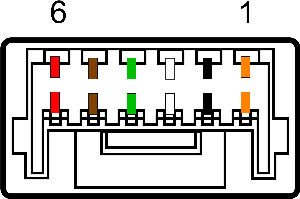
The camera is equipped with a 6-pin GPIO connector. The connector is a JST BM06B-NSHSS-TBT (LF)(SN), the mating connector is a JST NSHR-06V-S.
| Color | Pin | Line | Function | Description | Parameters | Min | Max | Unit |
|---|---|---|---|---|---|---|---|---|
| Orange | 1 | 0 | GPIO0 | Non-isolated Input/Output TXD (output) for 1.8 V UART |
Input Low Level | 0 | 1.4 | V |
| Input High Level | 2.6 | 24 | V | |||||
| Propagation Delay | 1 | µs | ||||||
| Output Low Current | 25 | mA | ||||||
| Output High Level | 0 | 24 | V | |||||
| Black | 2 | 1 | GPIO1 | Non-isolated Input/Output RXD (input) for 1.8 V UART |
Input Low Level | 0 | 1.4 | V |
| Input High Level | 2.6 | 24 | V | |||||
| Propagation Delay | 1 | µs | ||||||
| Output Low Current | 25 | mA | ||||||
| Output High Level | 0 | 24 | V | |||||
| White | 3 | 2 | GPIO2 | Non-isolated Input/Output | Input Low Level | 0 | 1.4 | V |
| Input High Level | 2.6 | 24 | V | |||||
| Propagation Delay | 1 | µs | ||||||
| Output Low Current | 25 | mA | ||||||
| Output High Level | 0 | 24 | V | |||||
| Green | 4 | 3 | GPIO3 | Non-isolated Input/Output | Input Low Level | 0 | 1.4 | V |
| Input High Level | 2.6 | 24 | V | |||||
| Propagation Delay | 1 | µs | ||||||
| Output Low Current | 25 | mA | ||||||
| Output High Level | 0 | 24 | V | |||||
| Brown | 5 | N/A | GND | Camera Power Ground | ||||
| Red | 6 | N/A | Vout | Camera Power Output | Output Voltage | 3.05 | 3.35 | V |
| Output Current | 120 | mA |
This section describes how to configure the camera's general purpose digital input and outputs (sometimes referred to as GPIO).
Use LineSelector to choose which of the 4 lines to configure. All the features listed beneath it are controllable on a per line basis.
Use Line Mode to control the direction - either Input or Output - of the selected I/O line.
Use LineInverter to control a logic inverter on the selected line.
LineStatus indicates the current status of the selected line. A checked status (enabled) indicates logic high. An unchecked status (disabled) indicates logic low. Since this node must be polled to get its status it should not be used as a real time control for reading internal signals.
LineStatusAll is a hexadecimal representation of all the line status bits (Line 0 status corresponds to bit 0, Line 1 status with bit 1, etc). This allows simultaneous reading of all line statuses at once.
Use LineSource to control what signal is output on the line when the Line Mode is set to output. The choices are:
Other Lines - creates a loop back
Exposure Active - indicates when the image sensor is exposing
Frame Trigger Wait - indicates when the camera is ready to accept a new Frame Start trigger
Summary Table
| Name | Interface | Access | Visibility | Description |
|---|---|---|---|---|
| Line Selector | IEnumeration | Expert | Selects the physical line (or pin) of the external device connector to configure | |
| Line Mode [Line Selector] | IEnumeration | Expert | Controls if the physical Line is used to Input or Output a signal. | |
| 3.3V Enable | IBoolean | RW | Guru | Internally generated 3.3V rail. Enable to supply external circuits with power. This is different than standard logic outputs in that it is comparatively slow to switch but can supply a more significant amount of power. This is only available on some pins. |
| Line Inverter [Line Selector] | IBoolean | RW | Expert | Controls the inversion of the signal of the selected input or output line. |
| Line Status [Line Selector] | IBoolean | RO | Expert | Returns the current status of the selected input or output Line |
| Line Status All | IInteger | RO | Expert | Returns the current status of all the line status bits in a hexadecimal representation (Line 0 status corresponds to bit 0, Line 1 status with bit 1, etc). This allows simultaneous reading of all line statuses at once. |
| Line Source [Line Selector] | IEnumeration | Expert | Selects which internal acquisition or I/O source signal to output on the selected line. LineMode must be Output. |
Digital IO Control Features
Line Selector
Selects the physical line (or pin) of the external device connector to configure
| Property | Value |
|---|---|
| Name | LineSelector |
| Interface | IEnumeration |
| Access | |
| Visibility | Expert |
| Enumeration Values |
|---|
| Line0 |
| Line1 |
| Line2 |
| Line3 |
Line Mode
Controls if the physical Line is used to Input or Output a signal.
| Property | Value |
|---|---|
| Name | LineMode [Line Selector] |
| Interface | IEnumeration |
| Access | |
| Visibility | Expert |
| Enumeration Values |
|---|
| Input |
| Output |
3.3V Enable
Internally generated 3.3V rail. Enable to supply external circuits with power. This is different than standard logic outputs in that it is comparatively slow to switch but can supply a more significant amount of power. This is only available on some pins.
| Property | Value |
|---|---|
| Name | V3_3Enable |
| Interface | IBoolean |
| Access | RW |
| Visibility | Guru |
Line Inverter
Controls the inversion of the signal of the selected input or output line.
| Property | Value |
|---|---|
| Name | LineInverter [Line Selector] |
| Interface | IBoolean |
| Access | RW |
| Visibility | Expert |
Line Status
Returns the current status of the selected input or output Line
| Property | Value |
|---|---|
| Name | LineStatus [Line Selector] |
| Interface | IBoolean |
| Access | RO |
| Visibility | Expert |
Line Status All
Returns the current status of all the line status bits in a hexadecimal representation (Line 0 status corresponds to bit 0, Line 1 status with bit 1, etc). This allows simultaneous reading of all line statuses at once.
| Property | Value |
|---|---|
| Name | LineStatusAll |
| Interface | IInteger |
| Access | RO |
| Unit | |
| Visibility | Expert |
Line Source
Selects which internal acquisition or I/O source signal to output on the selected line. LineMode must be Output.
| Property | Value |
|---|---|
| Name | LineSource [Line Selector] |
| Interface | IEnumeration |
| Access | |
| Visibility | Expert |
| Enumeration Values |
|---|
| Off |
| Line0 |
| Line1 |
| Line2 |
| Line3 |
| ExposureActive |
| FrameTriggerWait |
| SerialPort0 |
_242x41.jpg)