Input/Output Control
General Purpose Input/Output (GPIO)
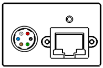
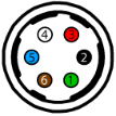
The camera is equipped with a 6-pin GPIO connector on the back of the case. The connector is a Hirose HR10A-7R-6PB, the mating connector is a Hirose HR10A-7P-6S(73).
| Diagram | Color1 | Pin | Line | Function | Description | Parameter | Min | Max | Unit |
|---|---|---|---|---|---|---|---|---|---|
|
Green | 12 | 3 | VEXT | External Input Voltage (DC) | Input Voltage Range | 9.5 | 24 | V |
| GPI | Non-isolated Input | Input Low Level | 0.9 | 1.4 | V | ||||
| Input High Level | 1.5 | 2.6 | V | ||||||
| Propagation Delay | 55 | nS | |||||||
| Black | 2 | 0 | OPTOIN | Opto-isolated Input | Input Low Level | 0 | 1.4 | V | |
| Input High Level | 2.6 | 24 | V | ||||||
| Input Current | 3.5 | 7 | mA | ||||||
| Propagation Delay Low to High | 22 | μs | |||||||
| Propagation Delay High to Low | 5 | μs | |||||||
| Red | 32 | 2 | VAUX OUT | Auxiliary Power Output | Output Voltage | 3.38 | 3.87 | V | |
| Output Current | 120 | mA | |||||||
| GPIO3 | Non-isolated Input/Output | Input Low Level | 0.9 | 1.4 | V | ||||
| Input High Level | 1.5 | 3.6 | V | ||||||
| Propagation Delay | 55 | nS | |||||||
| Output Low Current | 24 | mA | |||||||
| Output High Level | 0 | 24 | V | ||||||
| White | 4 | 1 | OPTOOUT3 | Opto-isolated Output | Output Low Current4 | 25 | mA | ||
| Output High Level | 3.3 | 7 | V | ||||||
| Propagation Delay Low to High | 36 | μs | |||||||
| Propagation Delay High to Low | 5 | μs | |||||||
| Blue | 5 | N/A | Opto GND | Opto-isolated Ground | |||||
| Brown | 6 | N/A | GND | Camera Power Ground | |||||
Measurement Conditions: Opto-Isolated I/O VCC=5 V, Rext = 1 kOhm, Non-Isolated Output: VCC=Internal 3.3 V, Rinternal = 4.7 k, Non-Isolated Input: Vpulse=3.3 V. Measured at 25°C ambient and camera top case temperature at ~55°C. Values are for reference only. They could vary depending on test conditions.
1—GPIO cable assembly wire colors
2—Dual function pin
3—Open drain output, requires pullup resistor
4—Output low level depends on the output voltage / pullup resistor combination