Input/Output Control
General Purpose Input/Output (GPIO)
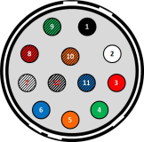
The camera has an 12-pin GPIO connector on the back of the case. The connector is a Hirose HR10 (Mfg P/N: HR10A-10R-12SB). The mating connector is a Hirose HR10A (Mfg P/N: HR10A-10P-12P).
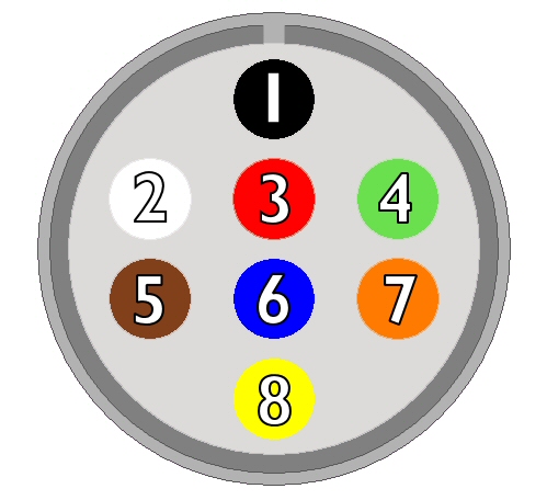
The custom model has an 8-pin GPIO connector on the back of the case.
| Small, Standard, and Large Case Models | ||||
|---|---|---|---|---|
|
||||
| Color | Pin | Line | Function | Description |
| Black | 1 | N/A | GND | DC camera power ground |
| White | 2 | N/A | POWER | DC camera power |
| Red | 3 | Line 1 | GPIO_OPT_OUT1 | Opto-isolated output (GPO1) |
| Green | 4 | Line 4 | GPIO_OPT_OUT2 | Opto-isolated output (GPO2) |
| Orange | 5 | Line 0 | GPIO_OPT_IN1 | Opto-isolated input (GPI1) |
| Blue | 6 | Line 3 | GPIO_OPT_IN2 | Opto-isolated input (GPI2) |
| White with black stripes | 7 | Line 2 | GPIO_TTL_IO3 | TTL input/output 3* |
| Red with black stripes | 8 | Line 5 | GPIO_TTL_IO4 | TTL input/output 4* |
| Green with black stripes | 9 | N/A | GND | DC camera power ground |
| Orange with black stripes | 10 | N/A | POWER | DC camera power |
| Blue with black stripes | 11 | Line 6 | 3.3 V OUTPUT | +3.3 V output, current 120 mA (nominal) - firmware enabled |
| Black with white stripes | 12 | N/A | OPTO_GND | Ground for opto-isolated I/O, not connected to camera ground |
| *When configured as output line format is open drain, not TTL. Users should attach their own external pull-up resistor. | ||||
| Custom Model | 97-02800-00100 | ||
|---|---|---|---|
|
|||
| Color | Pin | Function | Description |
| Black | 1 | IO | Opto-isolated input (default Trigger in) |
| White | 2 | O1 | Opto-isolated output |
| Red | 3 | IO2 | Input/Output/serial transmit (TX) |
| Green | 4 | IO3 | Input/Output/serial receive (RX) |
| Brown | 5 | GND | Ground for bi-directional IO, VEXT, +3.3 V pins |
| Blue | 6 | OPTO_GND | Ground for opto-isolated IO pins |
| Orange | 7 | VEXT | Allows the camera to be powered externally |
| Yellow | 8 | 3.3 V OUTPUT | Power external circuitry up to 150 mA |
_242x41.jpg)