Input/Output Control
General Purpose Input/Output (GPIO)
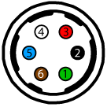
The camera is equipped with a 6-pin GPIO connector on the back of the case. The connector is a Hirose HR10A-7R-6PB, the mating connector is a Hirose HR10A-7P-6S(73).
| Diagram | Color1 | Pin | Line | Function | Description | Parameter | Min | Max | Unit |
|---|---|---|---|---|---|---|---|---|---|
|
|
Green | 12 | 3 | VAUX | Auxiliary Input Voltage (DC) | Input Voltage Range | 8 | 24 | V |
| GPI | Non-isolated Input | Input Low Level | 0 | 1.4 | V | ||||
| Input High Level | 2.6 | 3.6 | V | ||||||
| Propagation Delay | 1 | μs | |||||||
| Black | 2 | 0 | OPTOIN | Opto-isolated Input | Input Low Level | 0 | 1.4 | V | |
| Input High Level | 2.6 | 30 | V | ||||||
| Input Current | 3.5 | 7 | mA | ||||||
| Propagation Delay Low to High | 18 | μs | |||||||
| Propagation Delay High to Low | 9 | μs | |||||||
| Red | 32 | 2 | VOUT | Camera Power Output | Output Voltage | 3.05 | 3.35 | V | |
| Output Current | 120 | mA | |||||||
| GPIO3 | Non-isolated Input/Output | Input Low Level | 0 | 1.4 | V | ||||
| Input High Level | 2.6 | 24 | V | ||||||
| Propagation Delay | 1 | μs | |||||||
| Output Low Current | 25 | mA | |||||||
| Output High Level | 0 | 24 | V | ||||||
| White | 4 | 1 | OPTOOUT3 | Opto-isolated Output | Output Low Current4 | 25 | mA | ||
| Output High Level | 0 | 24 | V | ||||||
| Propagation Delay Low to High | 36 | μs | |||||||
| Propagation Delay High to Low | 18 | μs | |||||||
| Blue | 5 | N/A | Opto GND | Opto-isolated Ground | |||||
| Brown | 6 | N/A | GND | Camera Power Ground | |||||
Measurement conditions: Opto-Isolated I/O VCC=5V, Rext=1KOhm, Non-Isolated Output: VCC=5V, Rext=330 Ohm, Non-Isolated Input: VCC=3.3V. Measured over operating temperature range (-20˚C to +50˚C ambient temperature), unless otherwise noted.
1—GPIO cable assembly wire colors
2—Dual function pin
3—Open drain output, requires pullup resistor
4—Output low level depends on the output voltage / pullup resistor combination


