|
FLIR
Blackfly®S BFS-U3-200S6 |
Logic Block Control
For more detail, see TAN2016005 Using Logic Blocks
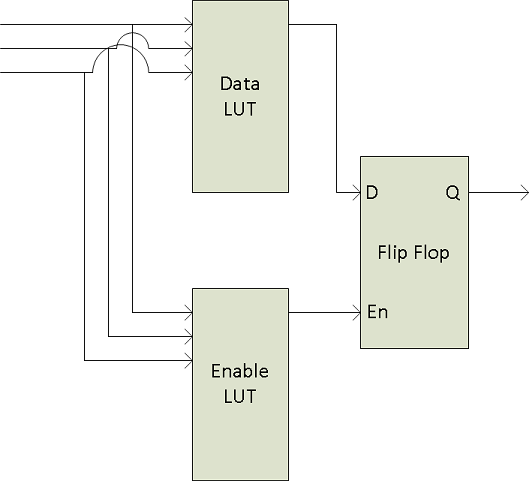
A Logic Block is a collection of combinatorial logic and latches that allows the user to create new, custom signals inside the camera. Each Logic Block is comprised of 2 lookup tables (LUT) with programmable inputs, truth tables and a flip flop output. There is a LUT for both the D input (Value LUT) and the enable input (Enable LUT) of the flip flop. Both LUTs have 3 inputs and thus have 8 configuration bits for their truth table.

To configure the LUTs first select either the Value or Enable LUT using the LogicBlockLUTSelector, then use the LogicBlockLUTInput to configure the different inputs into the LUT - note that the Value and Enable LUT share the inputs so setting the inputs on one will affect the other. The LogicBlockLUTInputSource selects the internal signal to be used and the LogicBlockLUTInputActivation selects what level or edge to be considered a positive input into the LUT. Once the inputs to the LUT have been selected the entries in the truth table can be configure either individually using the LogicBlockLUTRowIndex and LogicBlockLUTOutput or all at once using the LogicBlockLUTOutputValueAll
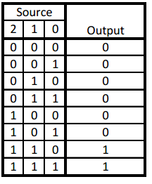
The following truth table show a simple AND of Input1 and Input2 while Input0 is not considered ("DON'T CARE").

To program this function into a LUT write the value of 0xC0 (1100 0000b) to the LogicBlockLUTOutputValueAll.
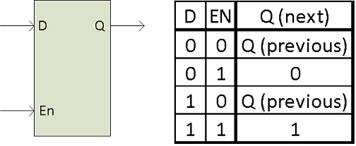
The details of the output Flip Flop output are shown in the following table. The previous value of the Value LUT will remain on the output until the Enable LUT is set at which point the output will be updated to the new value of the Value LUT. This allows latching of a given signal. To effectively bypass the output latch and pass the Value LUT signal through continuously simple program the Enable LUT truth table to all 1's (LogicBlockLUTOutputValueAll = 0xFF)

Summary Table
| Name | Interface | Access | Visibility | Description |
|---|---|---|---|---|
| Logic Block Selector | IEnumeration | Guru | Selects which LogicBlock to configure | |
| Logic Block LUT Selector [Logic Block Selector] | IEnumeration | Guru | Selects which LogicBlock LUT to configure | |
| Logic Block LUT Input Selector [Logic Block LUT Selector] | IEnumeration | Guru | Controls which LogicBlockLUT Input Source & Activation to access. | |
| Logic Block LUT Input Source [Logic Block LUT Input Selector] | IEnumeration | RW | Guru | Selects the source for the input into the Logic LUT. |
| Logic Block LUT Input Activation [Logic Block LUT Input Selector] | IEnumeration | Guru | Selects the activation mode of the Logic Input Source signal. | |
| Logic Block LUT Output Value All [Logic Block LUT Selector] | IInteger | Guru | Sets the value of all the output bits in the selected LUT. | |
| Logic Block LUT Row Index [Logic Block LUT Selector] | IInteger | Guru | Controls the row of the truth table to access in the selected LUT. | |
| Logic Block LUT Output Value [Logic Block LUT Row Index] | IBoolean | Guru | Controls the output column of the truth table for the selected LogicBlockLUTRowIndex. |
Logic Block Control Features
Logic Block Selector
Selects which LogicBlock to configure
| Property | Value |
|---|---|
| Name | LogicBlockSelector |
| Interface | IEnumeration |
| Access | |
| Visibility | Guru |
| Enumeration Values |
|---|
| LogicBlock0 |
| LogicBlock1 |
Logic Block LUT Selector
Selects which LogicBlock LUT to configure
| Property | Value |
|---|---|
| Name | LogicBlockLUTSelector [Logic Block Selector] |
| Interface | IEnumeration |
| Access | |
| Visibility | Guru |
| Enumeration Values |
|---|
| Value |
| Enable |
Logic Block LUT Input Selector
Controls which LogicBlockLUT Input Source & Activation to access.
| Property | Value |
|---|---|
| Name | LogicBlockLUTInputSelector [Logic Block LUT Selector] |
| Interface | IEnumeration |
| Access | |
| Visibility | Guru |
| Enumeration Values |
|---|
| Input0 |
| Input1 |
| Input2 |
| Input3 |
Logic Block LUT Input Source
Selects the source for the input into the Logic LUT.
| Property | Value |
|---|---|
| Name | LogicBlockLUTInputSource [Logic Block LUT Input Selector] |
| Interface | IEnumeration |
| Access | RW |
| Visibility | Guru |
| Enumeration Values |
|---|
| Zero |
| Line0 |
| Line1 |
| Line2 |
| Line3 |
| UserOutput0 |
| UserOutput1 |
| UserOutput2 |
| UserOutput3 |
| Counter0Start |
| Counter1Start |
| Counter0End |
| Counter1End |
| LogicBlock0 |
| LogicBlock1 |
| ExposureStart |
| ExposureEnd |
| FrameTriggerWait |
| AcquisitionActive |
Logic Block LUT Input Activation
Selects the activation mode of the Logic Input Source signal.
| Property | Value |
|---|---|
| Name | LogicBlockLUTInputActivation [Logic Block LUT Input Selector] |
| Interface | IEnumeration |
| Access | |
| Visibility | Guru |
| Enumeration Values |
|---|
| LevelLow |
| LevelHigh |
| FallingEdge |
| RisingEdge |
| AnyEdge |
Logic Block LUT Output Value All
Sets the value of all the output bits in the selected LUT.
| Property | Value |
|---|---|
| Name | LogicBlockLUTOutputValueAll [Logic Block LUT Selector] |
| Interface | IInteger |
| Access | |
| Unit | |
| Visibility | Guru |
Logic Block LUT Row Index
Controls the row of the truth table to access in the selected LUT.
| Property | Value |
|---|---|
| Name | LogicBlockLUTRowIndex [Logic Block LUT Selector] |
| Interface | IInteger |
| Access | |
| Unit | |
| Visibility | Guru |
Logic Block LUT Output Value
Controls the output column of the truth table for the selected LogicBlockLUTRowIndex.
| Property | Value |
|---|---|
| Name | LogicBlockLUTOutputValue [Logic Block LUT Row Index] |
| Interface | IBoolean |
| Access | |
| Visibility | Guru |
| 8/31/2017
© 2015-2017 FLIR® Integrated Imaging Solutions Inc. All rights reserved. Legal | Contact Support | Cookie Policy |
Blackfly®S BFS-U3-200S6 |
|
