|
FLIR
Blackfly®S BFS-GE-16S2-BD2 |
GPIO Electrical Characteristics
The output is open collector and thus requires a pull-up resistor to operate. The rise time and bias current will be determined by the resistor value chosen. If the camera is generating an output signal that approaches the rise time plus the fall time of the opto-isolated circuit, care must be taken to optimize the pull-up resistor chosen to minimize the rise time while still remaining within the current limits of the output circuit.
Operating Range
| Description | Minimum | Maximum |
|---|---|---|
| 3.3 V Output Current | 120 mA |
Non-isolated External Voltage Resistor Combinations
| External Voltage |
External Resistor |
Current |
|---|---|---|
| 3.3 V | 1.0 kΩ | 3.1 mA |
| 5 V | 1.0 kΩ | 4.8 mA |
| 12 V | 2.0 kΩ | 6 mA |
| 12 V | 2.4 kΩ | 5 mA |
| 24 V | 4.7 kΩ | 5.2 mA |
| 30 V | 4.7 kΩ | 6.5 mA |
| Values are for reference only | ||
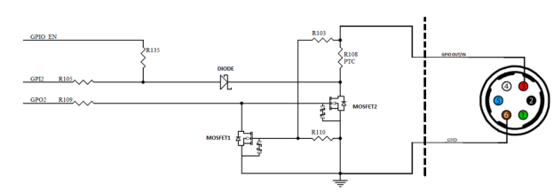
Non-isolated input and output circuit
| 8/13/2018
© 2015-2018 FLIR® Integrated Imaging Solutions Inc. All rights reserved. Legal | Contact Support | Cookie Policy |
Blackfly®S BFS-GE-16S2-BD2 |
|