|
FLIR
Blackfly®S BFS-GE-16S2-BD2 |
General Purpose Input Output (GPIO)
This test connects a special adapter to the device's external GPIO interface and performs a series of continuity tests to ensure that all of the communications pins are functional.
Pass/Fail Criteria
- All I/O pins must be able to input and output signals as per the device specification.
Measurement conditions: Opto-Isolated I/O VCC=5V, Rext=1KOhm, Non-Isolated Output: VCC=5V, Rext=330 Ohm, Non-Isolated Input: VCC=3.3V. Measured over operating temperature range (-20˚C to +50˚C ambient temperature), unless otherwise noted.
|
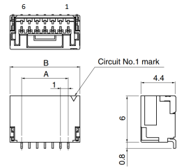
Note: Diagram is for reference only. |
| Color | Pin | Line | Function | Description | Parameters | Min | Max | Unit |
|---|---|---|---|---|---|---|---|---|
| Orange | 1 | 0 | GPIO0 | Non-isolated Input/Output | Input Low Level | 0 | 1.4 | V |
| Input High Level | 2.6 | 24 | V | |||||
| Propagation Delay | 1 | µs | ||||||
| Output Low Current | 25 | mA | ||||||
| Output High Level | 0 | 24 | V | |||||
| Black | 2 | 1 | GPIO1 | Non-isolated Input/Output | Input Low Level | 0 | 1.4 | V |
| Input High Level | 2.6 | 24 | V | |||||
| Propagation Delay | 1 | µs | ||||||
| Output Low Current | 25 | mA | ||||||
| Output High Level | 0 | 24 | V | |||||
| White | 3 | 2 | GPIO2 | Non-isolated Input/Output | Input Low Level | 0 | 1.4 | V |
| Input High Level | 2.6 | 24 | V | |||||
| Propagation Delay | 1 | µs | ||||||
| Output Low Current | 25 | mA | ||||||
| Output High Level | 0 | 24 | V | |||||
| Green | 4 | N/A | VExt | Camera Input Power |
4.0 |
5.5 |
V | |
| Brown | 5 | N/A | GND | Camera Power Ground | ||||
| Red | 6 | N/A | Vout | Camera Power Output | Output Voltage | 3.05 | 3.35 | V |
| Output Current | 120 | mA |
Test Stages and Configurations
| Test Stage | Test Configuration |
|---|---|
| U6 | STC I |
Additional Configuration
- GPIO Test Adapter.
| 8/13/2018
© 2015-2018 FLIR® Integrated Imaging Solutions Inc. All rights reserved. Legal | Contact Support | Cookie Policy |
Blackfly®S BFS-GE-16S2-BD2 |
|